Texas InstrumentsUnited States

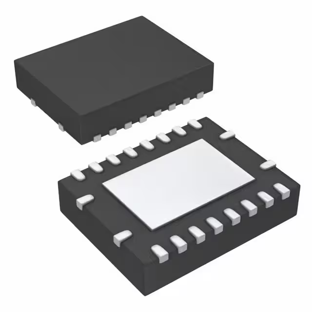
IC REG CTRLR BUCK 20VQFN
TPS40170RGYR is a 4.5V to 60V wide-input synchronous PWM buck controller with programmable switching frequency from 100kHz to 600kHz, in a 20-pin VQFN package, featuring UVLO, OCP, SCP, and thermal shutdown, operating from -40°C to 125°C.Checked against the datasheet
All alternatives
View full report2 alternatives on file. Sign in to view them.
Technical parameters
Key specs
TopologyBuck
Outputs1
Input voltage4.5 ~ 60 V
Switching frequency100 ~ 600 kHz
Datasheet-verified parameters
23 items| Parameter | Value and test conditions | Source |
|---|---|---|
| Topology | Synchronous PWM Buck | |
| Outputs | 1 | |
| Input Voltage Range | 4.5 V to 60 V | |
| Switching Frequency | 100 kHz to 600 kHz | |
| Package | VQFN (RGY), 20-Pin, 3.5 mm × 4.5 mm | |
| Operating Temperature | -40°C to 125°C |
All parameters (22)
| Power | |
|---|---|
| Voltage - Supply (Vcc/Vdd) | 4.5V ~ 60V |
| AC and DC characteristics | |
| Frequency - Switching | 100kHz ~ 600kHz |
| Environment and package | |
| Mounting Type | Surface Mount |
| Operating Temperature | -40°C~125°C(TJ) |
| Package | Tape & Reel (TR); Cut Tape (CT); Digi-Reel® |
| Package / Case | 20-VFQFN Exposed Pad |
| Supplier Device Package | 20-VQFN (3.5x4.5) |
| Other | |
| Base Product Number | TPS40170 |
| Clock Sync | Yes |
| Control Features | Current Limit, Enable, Frequency Control, Power Good, Soft Start, Tracking |
| Duty Cycle (Max) | 95% |
| Function | Step-Down |
| Mfr | Texas Instruments |
| Number of Outputs | 1 |
| Output Configuration | Positive |
| Output Phases | 1 |
| Output Type | Transistor Driver |
| Product Status | Active |
| Serial Interfaces | - |
| Series | - |
| Synchronous Rectifier | Yes |
| Topology | Buck |
Pinout and package
Figure 4-1. RGY PACKAGE, QFN-2…
| Pin | Name | Function | Source |
|---|---|---|---|
| 1 | ENABLE, Enable pin, active high, low level enters low-power shutdown mode | ||
| 2 | SYNC, Synchronization pin, bi-directional, for frequency synchronization | ||
| 3 | M/S, Primary/Secondary mode selector pin, for frequency synchronization mode selection | ||
| 4 | RT, Oscillator frequency setting pin, sets switching frequency via resistor | ||
| 5 | SS, Soft-start pin, sets soft-start time via capacitor | ||
| 6 | TRK, Voltage tracking pin, for output voltage tracking | ||
| 7 | FB, Feedback pin, negative input to error amplifier | ||
| 8 | COMP, Error amplifier output pin, connects compensation network | ||
| 9 | AGND, Analog ground pin | ||
| 10 | VDD, 3.3V regulated output pin | ||
| 11 | PGOOD, Power good indicator pin, open-drain output | ||
| 12 | ILIM, Overcurrent limit setting pin, sets overcurrent threshold via resistor | ||
| 13 | PGND, Power ground pin | ||
| 14 | LDRV, Low-side FET gate driver output pin | ||
| 15 | VBP, 8V regulated output pin, for gate driver | ||
| 16 | SW, Switching node pin, connects to synchronous buck converter switching node | ||
| 17 | HDRV, High-side FET gate driver output pin | ||
| 18 | BOOT, Bootstrap capacitor node pin, for high-side FET gate driver | ||
| 19 | VIN, Input voltage pin, controller and DC/DC converter input | ||
| 20 | UVLO, Undervoltage lockout pin, sets threshold via resistor divider |
Documents
Datasheet-verified content is extracted by AI from the manufacturer datasheet. Click a page number to view the original.